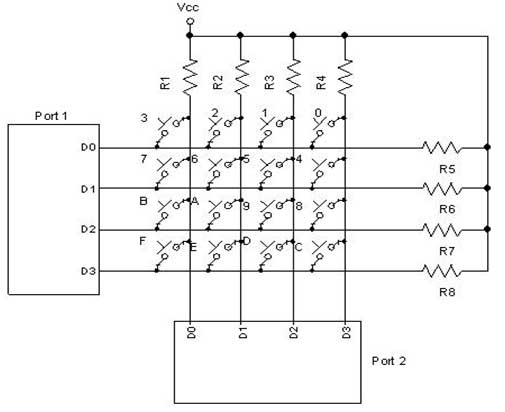
Serial 4 X 4 Keypad Schematic

Introduction Keypads are used in all types of devices, including cell phones, fax machines, microwaves, ovens, door locks, etc. Driver Onda M1hs Per Windows 7. They’re practically everywhere. Tons of electronic devices use them for user input. So knowing how to connect a keypad to a microcontroller such as an Arduino is very valuable for building many different types of commercial products. At the end, when all is connected properly and programmed, when a key is pressed, it shows up at the Serial Monitor on your computer.

Whenever you press a key, it shows up on the Serial Monitor. But for now, for simplicity purposes, we start at simply showing the key pressed on the computer. Pathfinder Full Movie on this page.
#include Keypad.h>const byte ROWS = 4; const byte COLS = 4; //define the symbols on the buttons of the keypads char Keys. (4)Open the serial Monitor. 1x4 Membrane Keypad W/ Arduino. * 1x4 Keypad w/ primary pin attached to Ground and 1-4 keys attached to PINS 9-12 * Serial Monitor used for output.
For this project, the type of keypad we will use is a matrix keypad. This is a keypad that follows an encoding scheme that allows it to have much less output pins than there are keys. For example, the matrix keypad we are using has 16 keys (0-9, A-D, *, #), yet only 8 output pins. With a linear keypad, there would have to be 17 output pins (one for each key and a ground pin) in order to work. The matrix encoding scheme allows for less output pins and thus much less connections that have to be made for the keypad to work.
In this way, they are more efficient than linear keypads, being that they have less wiring. Understand the Keypad One of the most mysterious things about these keypads is that they usually come with no documentation, so a user is left to figure out the pin configuration for him or herself. However, we at this site, have figured it out. With the keypad facing up so that the keys are up and facing you, from left to right, the 1st 4 pins are the row pins and the last 4 pins are the column pins. Connections of this project are straight and simple as shown above. • Connect pin 1 of keypad to pin 9 of Arduino.
Comments are closed.